The purpose of this lab was to practice geometric correction. This was our first time working with the image preprocessing method. This process is typical done before any information can be extracted from an image. Geometric correction is performed because many satellite images are not collected in their proper planimetric position, also known as coordinates. It does away with most of the distortion in the original satellite image and creates a more accurate images that we can use to extract reliable and accurate information.
In this lab we used:
- USGS 7.5 minute digital raster graphic image of the Chicago Metropolitan Statistical Area to correct a Landsat TM image of the same area.
- Landsat TM image for eastern Sierra Leone to correct a geometrically distorted image of the same area.
Methods
Part 1: Image-to-map rectification
In the first part of this lab we worked with the Chicago area. We had a raster image that we needed to geometrically correct and a reference image which was a topographic map. Two views were opened in order to view both images at once. The distortion was visible, but not greatly so. In order to create ground control points (GCPs) we needed to click on the Multispectral tab in order to activate the raster processing tools for multispectral imagery. From here we chose the Control Points option. We needed to click through some windows that opened in order to set parameters for the image. Most of these we kept as their default settings. One window that pops up tells us what coordinate system the images is in and it also says "model has no solution". This means we need to add GCPs in order to create a solution for the model.
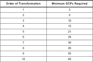
After clicking through multiple windows, we are now in the Multipoint Geometric Correction window. On the left is the Chicago satellite image that needs to be corrected. On the right is the Chicago reference image that is in the proper planimetric position. Now we needed to create a minimum of three GCPs for this image because it has a 1st order of transformation. There are different orders of transformation and in order to decide on which fits for an image we need to determine how many GCPs are needed in order to have a total RMS error below 1. In the case of the Chicago images we need a minimum of three GCPs which means it is the first order of transformation. Below in Figure 1 is a graph that was used in order to help determine that answer. Also below in Figure 2 is how the two Chicago images were seen in the Multipoint Geometric Correction window.
 |
| Figure 1: Order of transformation table to help determine the minimum GCPs required. |
 |
| Figure 2: Left satellite image of Chicago to be geometrically corrected. Right image of Chicago for a reference. |
We created four GCPs which created the dialogue stating "Model solution is current". In the results section is Figure 3 which shows the four GCPs and the total RMS error which is below 2.0. Now that the image is geometrically corrected we needed to save the new image. Also in the results section is Figure 4 which are side by side images of the original Chicago image and the corrected image.
Part 2: Image to image registration
For our next task we needed to geometrically correct and image with a reference image rather than a reference map like we used in part 1. We imported the images in the same manner as in part 1, except for one part. The Polynomial Model Properties window lets us choose the polynomial order for the image which sets the minimum amount of GCPs required to get the dialogue "Model solution is current". Instead of a 1st order like we did in the part 1, we set it to the 3rd order. This means we need a minimum of 10 GCPs in order to correct the image.
We created a total of 12 GCPs for these images and then made sure the RMS error was below 1, with below 0.5 being ideal. In Figure 5 in the results section is an image of the twelve GCPs along with the total RMS error of 0.26. One other thing we did differently with part 2 was when we saved the newly corrected image. Instead of choosing nearest neighbor for the resampling process, we chose billinear interpolation. We used this because it produces a more accurate image rather than using nearest neighbor. The result of this correction is seen in Figure 6 in the results section.
Results
| Figure 3: Four GCPs for the Chicago area with a total RMS error of 0.026 |
 |
| Figure 4: The original Chicago image is on the left. The geometrically corrected image is on the right. |
 |
| Figure 5: 12 GCPs for the Sierra Leone image with a total RMS error of 0.26. |
 |
| Figure 6: The original image of Sierra Leone is on the left. On the right is the geometrically corrected image. |
Conclusions
Overall, this lab taught us a very valuable skill. Given that many satellite images a not in their proper planimetric position, geometric correction needs to be done quite often. Once it is practiced a couple of time the process becomes more understandable and practical. It is vital to use this tool in order to get accurate data in the final product.
No comments:
Post a Comment